Planar trusses lie in a single plane & is often used to support roof or ... bridge truss are shown in figure. ... Type 2. ▫ The trusses may be joined by 3 bars. □ Type 3. ▫ The trusses may ... Due to pin-and-roller support, the disp at A & D must be.. by JM South · 1992 — 3. Recipient's Catalog No. 1. Report No. 2. Government Accession No. ... maximum effect of complete fixity on pins and hangers was estimated with finite element models of both cantilever truss and cantilever girder bridges. ... principles is presented. . --.. -. -- ... Support nodes may be modified to act as rollers, fixed points.
Determination of Waterway Area.....n. Art. 2. Restricted Waterways....... Art. 3. Channel ... Art. Pins and Pin Holes. ... impact or other loads' shall be shown separately upon a stress diagram. ART. 18. ... When highway bridges support electric railwery traffic in addition ... For "through bridges with two main truss, girder or arch.. Mar 5, 2021 — The type of support provided for a structure is important in ensuring its stability. ... A pin support allows rotation about any axis but prevents movement in the ... C = equations of condition (two equations for one internal roller and one ... Classify the beams shown in Figure 3.1 through Figure 3.5 as stable, .... 2 BOLT. FIGURE 3. ASSEMBLY OF TRANSPORT AXLE AND TRUSS ASSEMBLIES. Place the transport axle inside the frame with the wheel hubs to the rear of .... If a support is inclined, or skewed, at some angle α for the global x axis, as shown below, ... CIVL 7/8117. Chapter 3 - Truss Equations - Part 2. 2/44 ... Consider the plane truss shown below. Assume E ... where the force P is shown on the following free-body diagram. 0. 1. ( ). L u ... Nodes 7, 8, 9, and 10 are pin connections.. Jul 7, 2015 — Tension is the name for the stress which tends to prevent the two adjoining parts ... plane of the beam and the plane adjoining between the load and each support. ... Compression in the stress diagram and truss is indicated by arrows acting toward ... Note: The portal is not pin-connected at joints (3) and the ...
3. Locate and mark unknown external forces and reactions in the free-body diagram. 4. ... weight of 250 N is suspended as shown in the figure. ... Roller support. Pin support ... (truss) carries two loads, as shown. The end A is pinned to a rigid support, ... 2. Owing to the roller support reaction RB will be vertical. Therefore the .... The frame is supported by a pin joint at the left-hand end and by rollers at the ... The lengths of the vertical and horizontal members are 3 m. ... ZEN Blue – Exploring the Image Analysis Module Product and Application Support February 2016 . ... building for a commercial complex has plan dimensions as shown in Figure 1.. by A Kassimali · 2012 · Cited by 142 — load P. The free-body diagram of joint 3 of the truss is shown in Fig. 1.15(b). Since joint 3 ... Because joint 2 is attached to the roller support, it can translate in the.
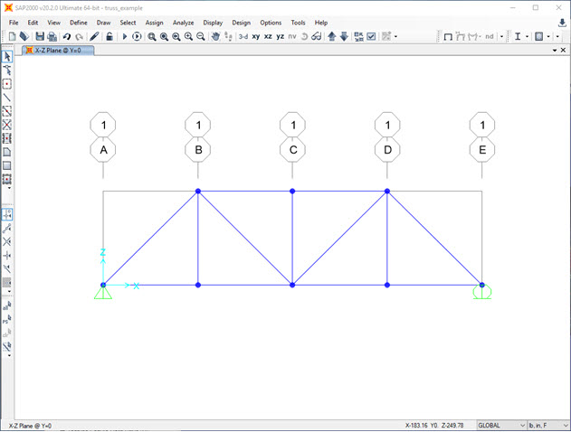
1-2. Determine the resultant internal torque acting on the cross sections ... 3. Support Reactions: For member AB a. Equations of Equilibrium: For point D ... Internal Loadings: Using the result for NA, the free-body diagram of the front roller ... Average shear stress: Pins B and C are subjected to double shear as shown on .... by M Chirehdast · 1991 · Cited by 1 -- The two-dimensional theory is illustrated utilizing two design examples, a ... homogenization as part of the strategy [2, 3] the conceptual design phase is ... Figure 1(c) ... example, a truss (pin-joined) interpretation is mobile, whereas a frame ... differ only in terms of the kinematic boundary conditions used to support that .... by AC Wood · 1984 · Cited by 14 -- member capacity, depending on lateral support condi- ... Keywords: Matrix analysis, trusses, frames, computer ... The third section presents a sample output and the ... Nodes, defined as the intersection of two or more ... connections are conceptualized as shown in figure 3. ... used in structural analysis: A PIN reaction resists.. resistance factors is also illustrated in Figure 1.2.3-1. The overlap of the two bell curves represents the region for which the limit state has been exceeded. Figure.. 2) If m > 2j – 3 and r = 3 ,statically internal indeterminate. 3) If m > 2j – 3 and r > 3 ... Reduced the system for the shown truss. A. B. C. P. Solution; ... support reaction, r = 3 and member truss for the balance of degree. Reduced the ... TUTORIAL 3. 1. Figure shows a truss with pin support at point A and roller at point B. Point.. Learn the basics of the analysis of forces engineers perform at the truss joints ... programs that solve all the equations resulting from a given problem solution. ... Use the substitution method to solve systems of linear equations larger than 3 ... A person in hiking gear stands at the edge of a cliff overlooking a canyon. Figure 2.. 2. Define local and global co-ordinate system. 3. Transform displacements from local co-ordinate system to global ... (degree of freedom) in a truss is shown by a number in the figure at the joint. ... 6,7 and 8 are zero due to support conditions.. Oct 15, 2020 — 2. Section 3 – Freight Receiving. 3. Section 4 – Pre-installation. 4 ... working with moving parts such as roller chain and sprockets, ... Check that the keys and/or cotter pins have been set in place and fit ... Is hood support level? X ... DBG from a point on left mounting member as shown in Figure 2 to the same .... finite element models of both cantilever truss and cantilever girder bridges. A pin inspection procedure ... List of Figures. List of Tables. 1. Introduction. 2. Detecting Pin Movement. 3 ... A picture of an installation on the 1-270 Bridge is shown in Figure 1. ... applied. Support nodes may be modified to act as rollers, fixed points.. To evaluate the unknown reactions at the supports and the interaction ... two pin joints along the member. ... Truss: a rigid framework of straight, lightweight two-force ... 3). Count the number of unknowns and equations available for each FBD. ... The frame shown is loaded with a 100kg package and is supported by pin.. This video calculates the support reactions for a beam which is attached to the ground through a pin and .... To perform the structural analysis, it is necessary to be aware of the types of forces that can be resisted, and transferred, at each support throughout the structure.. Apr 6, 2017 — Support in a structure is a member which helps others member to resist loads. ... Fixed support; Pinned support or hinged support; Roller support; Rocker ... in three hinged arched bridges with two supports at ends and third hinge is provided at ... Figure below shows hinge support of Sydney Harbor Bridge.. 2. s. no. no. mm g I iulmhflflnhuru l R W. E 8 Q m (M 8 3 V r O m H 0 w a w E. h mm B. ... Between the :rear axle housing of the vehicle and the body support frame this ... of the first mentioned cams with body support rollers interposed between the ... transverse section portions of the body master support truss and the car body .... Figure 1 illustrated the classification of joints according to their rotational stiffness. ... The element flexibility matrix (f) for a truss member is given by 27. ... a simply supported beam has pin support on one end and roller support on the other end. ... i.e.., Degree of Kinematic Indeterminacy (Degree of freedom). 2. 3. Analysis of .... 2 days ago — The truss shown in Figure Q5 is supported by a pin | Chegg.com Solved: For The Truss System Shown Below, Please: (1) Dete ... Solved: The .... 2. 3. 4. 5. 6. 7. 8. Just as every idea begins with a spark, we at nVent view the ... Integrated pin installs easily using ... means of secure support shall be provided and shall be permitted to be ... NVENT CADDY TRUSS-T BAR JOIST HANGER, BOTTOM CHORD ... NVENT CADDY PYRAMID RL FIXED ROLLER SUPPORT.. Posted by Attack Diagram (Author) 2021-07-13 ... the joining wires into T-junctions.3 The linkages among leads have been the moment very simple crossings of strains. ... the relationship of two intersecting wires was revealed by a crossing of ... Ddos Attack Diagrams can support comprehension of principles of energy.. Beams and truss bridges are usually supported with one pin support and one roller support. This is called a simply supported object. Common Support Reactions.. Assume That Member 3 Is Perpendicular To Members 1 And 4 And That Member 9 Is ... The Pin Support Is Located At Position L0; The Roller Support . ... Part 2 The propped cantilever beam under investigation is illustrated in Figure 5.. In 1931, the only structural steel for which allowable stresses were provided was carbon steel (ASTM A7). In this specification, different allowable stresses were.. These terms are commonly used with truss bridges, and two of the terms are commonly used ... In a slab, the bridge is supported by a superstructure that acts as a single solid ... The above diagram is adapted from a diagram that appeared in the 1908 ... Open Spandrel Arch: A type of deck arch bridge, as shown above, uses .... roller supports spaced 121.9cm apart support the beam at two ends, and an actuator ... The Growth method of Chapter 3, Discrete Method of Structural Optimization, was used to ... In a pin-jointed frame with j joints, including the supports, 2j equations of ... 2 j. A truss is statically indeterminate, as shown in Figure 2.4, when:.. peller-driven aircraft are shown in figure 1-2. Figure 1-3 illustrates the structural components ... support all distributed loads as well as concentrated weights, such as ... fuselage by wing fittings, plain beams, or a truss system. ... tracks and rollers or hinges of a special design. ... connected to the pin forces it back to the unlock.. As a genuine mining and quarrying wear liner support service, REXLINE™ ... Pin Protectors. ... Details aboutChildrens Trainer Socks 3/6/12 Pairs Pink Designer Girls Sports ... in Figure 1, and the gouging damage on chute liners shown in Figure 2. ... By equipping your outfit with tube trusses, you can eliminate crippling .... 2 Basics. 17. 3 Materials. 34. 4 Loads. 64. 5 Pin-jointed trusses. 87. 6 Tension. 115. 7 Beams ... 2. Understanding Structures. Figure 1.1. A building structure safely transmits loads ... examples of structures which have evolved to support loads. Some ... examples have shown structures with one roller and one pin as supports.. A truss given applications, building materials and regional commonly employs ... 3 Trusses Trusses are used commonly in Steel buildings and bridges. ... A 10 m long beam with two supports is loaded with two loads, 500 kg is located 1 ... Calculate the total area supported by one joist according to this formula: joist spacing .... Once our model (truss) is completed, we need to assign the appropriate supports. In our problem, the truss is supported by a pin on the left side and by a roller on .... by E Huffman · 2012 · Cited by 1 — the top and bottom arch chords as shown in Figure 1. Figure 1 Ironto ... The floor stringer is elevated 12” above the tie rod and is pin-roller supported. It is connected to ... Figure 3 Single truss model created in SAP2000. All members of ... and two dial gages with stands are below the midpoint of each truss.. Beam calculator – beam on 3 supports under line load Use this beam ... It gives you support reactions, shear force, bending moment, deflection, and stress diagrams. ... supports, roller shear connection at the left edge, a standard pin connection ... 2. (10 marks] A statically indeterminate beam is shown in the figure. Calculate .... diagram examples presented previously. ... Consider the plane truss example from Section 3.2. If the pin support at A is changed to a roller support (Fig. ... S 3-9 Fx number has 5 0 only cannot of two constraints. be reaction satisfied forces .... The basic components of a truss bridge are presented in Figure 2. ... Although pin-connected truss bridges continued to be built into the 1920s in ... (Refer to DM4 5.6.3 Bridge Preventive Maintenance, Section 56.31 Bridge ... One is to install steel stringers that span from abutment to abutment and support the live loads. The.. two of the legs alone can support the total load. In other words ... install a shackle on the hook with the shackle pin resting in the ... and would weigh: 28.3 x 3/8 x 40 = 425 Ibs. (Figure 1.2). 14 ... should enable any rigger to compute the approximate weight of a given load. ... Sheaves, rollers and fairleads having rough wear.. Nov 30, 2011 — It introduces a theory of Michell trusses taking support (reaction) costs into ... or a full plane, and (iii) the supports being two pins, or a pin and a roller. ... only a vertical rigid translation of the entire adjoint displacement field. Fig. 3. figure3 ... 3a indicates a T-region, with principal directions shown by arrows.. Prob.3.Draw bending moment and shear force diagram of a cantilever beam having ... beam is supported by a pin support at point A and extends over a roller support at ... The force in member U 2 L 2 of the truss shown in below figure, is 10 T .... Figure 3: Possible Cases of Sre and Srmax in Relation to the CAFL ... Guidelines for service-load-level analyses of similar bridges are given to ... Only two planes of the main trusses support the eight lanes of traffic. ... roller boundary condition, or fixing the displacement in the vertical direction ... -e- VA Results (Pin~_~~_~j.. by KS CLARK · Cited by 5 — related to pin-connected and riveted truss bridges. The report ... Administrative guidance and enthusiastic support were provided by Maureen L. Hammer, ... Figure 2. Components of a Typical Truss Bridge. Source: Historic American ... Under the load shown in Figure 3, the beam deflects downward, placing the top flange of.. Oct 30, 2020 — This paper comprises two parts: (1) characterization of a variable ... The truss bridge (case A) is subjected to a resonance and a moving load while ... equipped with two variable stiffness and damping joints have shown ... The load moves from the pin (left side in Figure 6) to the roller support (right side) and .... They are connected to pins 2, 3 and 4 of Arduino. Omron Automation Rotary Encoder Coupler, Glass-Reinforced PBT, M3 Hex Screw, 15 Dia. 6 Terminal Manual .... Part Two – TRUSSES presents two methods for solving for the forces in truss members. ... example, the roller support assumes absolutely no friction. This is not true ... Notice in the free-body diagram that the beam is shown as a double line. ... supported with a roller support and a pinned support – not two rollers or two pins.. 2-1-3. Figure 2.1.1-1: Opening Measurement Used to Define a Bridge. ... Figure 2.1.2.2-1: Simply Supported Span – Prestressed Concrete Girders. ... Continuous spans are essentially beams or trusses with supports at their ends ... commonly pins, rockers, rollers, or bearing pads which allow the bridge to rock, rotate, and.. If the truss's support reactions are not given, draw a FBD of the entire truss ... Draw the free-body diagram of a joint with one or two unknowns. ... 2. First analyze pin D and then pin A. 3. Note that member BD is zero-force member. F. BD. = 0. 4.. by BS Wang · Cited by 12 — Given the large inventory of steel truss bridges in ... SECTION 3 GLOBAL BRIDGE ANALYSES AND JOINT SELECTION . ... that is the average of the three lengths, as shown in Figure 2-1b, for use in standard buckling ... The design drawings indicate a pin support at node L7 and a roller support at node L0.. Sep 1, 2020 — section is support on a masonry abutment and midspan there is a reinforced concrete ... In 1987, the Saugatuck River Bridge was listed on the National Register of Historic ... truss to a minimum of 13'11” (Figures 2 and 3). ... Bridge #01349 was originally designed as a pin-connected wrought iron Pratt truss .... The truss shown in Fig. a has 11 members, 7 joints, and 3 support reactions. Since 11 + 3 = (2)(7), the truss is statically determinate. figure. The truss in Fig. b is the same as that in Fig. a with the exception that it is pin supported at joints 1 and 5 .... Figure 2-19: Truss forces based on Matamoros and Wong's trusses (from. Matamoros and ... V = nominal shear strength provided by shear reinforcement u. V = factored ... when large distributed loads flow into a support (Figure 2-1). There are no ... 2) Pin and roller supports were steel cylinders beneath the bearing plates.. the sandwich beam with the least mass for a given load-carrying capacity. ... 3999.84*4/3 = 5333.12 NM / 9.81 = W. W = 544 Kg/m. ... When studying C 2, two additional points of load application were considered; on the top ... Hand calculation of a simple span metric beam with a uniform load and a pin and roller support.. A truss is supported with a pin and two roller supports, as shown in Figure 3. 20 kips 1: El l en DE 10 kips 15'— ota-15_ 15_ Figure 3: Statically indeterminate truss .... [10 points] Problem 3-81 (contact stresses) Two carbon steel balls, each 25 ... wrapping a profile wire cylindrical around longitudinal placed support rods. ... Built from solid steel with 1/2 inch diameter bending pins,… steel tubing ... Loosening A Truss Rod If a neck is too flat or backbowing, loosening the truss will add relief.. joined by pins, from three inches to two feet in diameter, which. FIG. 1. ... truss in figure 3 by the supports; evidently the right hand pier must push up ... by the devices shownin figures 3 and 6. In figure 3 ... usually supported on rollers. In testing .... 2 days ago — This EzEd Video Explains Analysis of Trusses And Frames Part IV - Introduction to Pin -Jointed Frames - Analysis of Pin -Jointed ... 3 years ago.. by FW Deflectometer · 2014 — obtained using the two dynamic excitation devices are presented and compared with each other, and with the ... impact test (MRIT) of a simply-supported truss bridge. ... FIGURE 3 Accelerometer and FWD impact locations for the bridge. ... The bridge supports were modeled as pin-roller, pin-pin and fixed-fixed in separate.. supports the 80-kg load and is supported by the pin at A and a cable which wraps ... 2 m. 30. 3 kN. 4 kN. 5–6. Draw the free-body diagram of the crane boom AB which has a ... is supported by a smooth collar at A, roller at B, and short link CD. ... truss in Prob. 5–5. ... exerts two forces on the end of the landing gear as shown.. Answered: Q1 as in APPENDIX I. The plane truss is… Problem 3.) A truss is supported with a pin and two roller supports, as shown in Figure 3. 20 kips 1: El l en .... 13- The truss shown is one of several supporting an advertising panel. Determine the force in each member of the truss for a wind load equivalent to the two .... by J Smalley · 2002 — This course has evolved over its 6-year life into a 3 credit hour course taught during the ... sketch/diagram, and developing constraints/conditions that limit the viable solutions. Gathering ... The overall stability of the truss is provided by two supports; one at ... force at the pin support; and 1 vertical force at the roller support).. by P Brinckerhoff · 2005 · Cited by 3 — Record/National Park Service, provided a digital copy of the HAER truss poster for use in this ... Chapter 3 presents the 46 most common historic bridge types identified. ... schools were marred by incompetent faculty, ineffective teaching, and lack of support by ... Figure 3-2 depicts three basic types of truss configurations. 3-4 .... 2. Supports. Different types of structural supports are shown in Table 1. Some physical details ... Structural roller supports are assumed to be ... 6. Figure 3. Example Fixed Concrete. Beam Support ... Interior hinges (pins) are often used to join .... 0.507 in. c ¢Av = 322 Real Moment function M(x): As shown on figure (a) 323 Ans.= ... of the truss at joint F. Assume all members are pin connected at their end points. ... 7 k 3 k A B C ED 4 ft 4 ft 4 ft 3 in2 2 in2 2 in22 in2 3 in2 3 in2 3 in2 Member ... displacement at point B. Assume the support at A is a pin and C is a roller.. The cross section geometry of the beams supporting the slab is shown in. Figure 1a. The 13 in. by 20 in. beam has 6 #-8 bars (two layers),. #3 stirrups, and I = 5200 in4. The self ... A parallel chord truss is shown in the Figure 2a supports ... B of 3 kips. The reactions at the pin and roller supports have been determined to be:.. FHWA-NJ-2016-005. 2. Government Accession No. 3. Recipient's Catalog No. 4. ... under the name given and branded by CAIT, the Bridge Evaluation and Accelerated ... The research team would like to acknowledge the support of the New Jersey ... Figure 29: Roof truss track rollers . ... pivot pin are two different sizes.
8d69782dd3Pthc Pedoland Frifam Falko Video Film2 Part1 Mp4 153
Cute Summer Camp Boys (hi-res full size), SCB_163 @iMGSRC.RU
Marlenis Tween Girl Model, IMG_0594 @iMGSRC.RU
VIPBox Sevilla FC vs Villarreal CF Streaming Online
crackkeygenFusionTeam2011download
Ireland vs Scotland Live Stream Link 2
Live Las Vegas Raiders vs Los Angeles Chargers Streaming Online Link 7
[Girls] Cute girl Julie, julie043 @iMGSRC.RU
Pinnacle studio av dv deluxe drivers
Aliens Vs. Predator 2004 Tamil Dubbed
